Running servo motor using flex sensor

Programming and Somatic senseUpdated:

This is a hands-on project where bending a flex sensor drives a servo motor. The equipment used is as follows :

PCA9685 (Motor Driver)
DS3225(25kg Servo Motor)
RDS5160(60kg Servo Motor)
ESP32 Flex Sensor
10kgΩ Resistor

1. Exercise overview

Overview

Check the movie

We’ll practice reading how much a flex sensor is bent and converting that into a servo rotation angle.

The video above shows the final outcome.

A flex sensor is film-shaped, so you can attach it to soft materials or objects that can bend.

The key idea is turning a tangible hand movement into a physical effect—rotating a motor.

GitHub link

You can download the code from the  GitHub link.

Click the green “Code” button, then download the ZIP to get started.

2. Preparing the environment

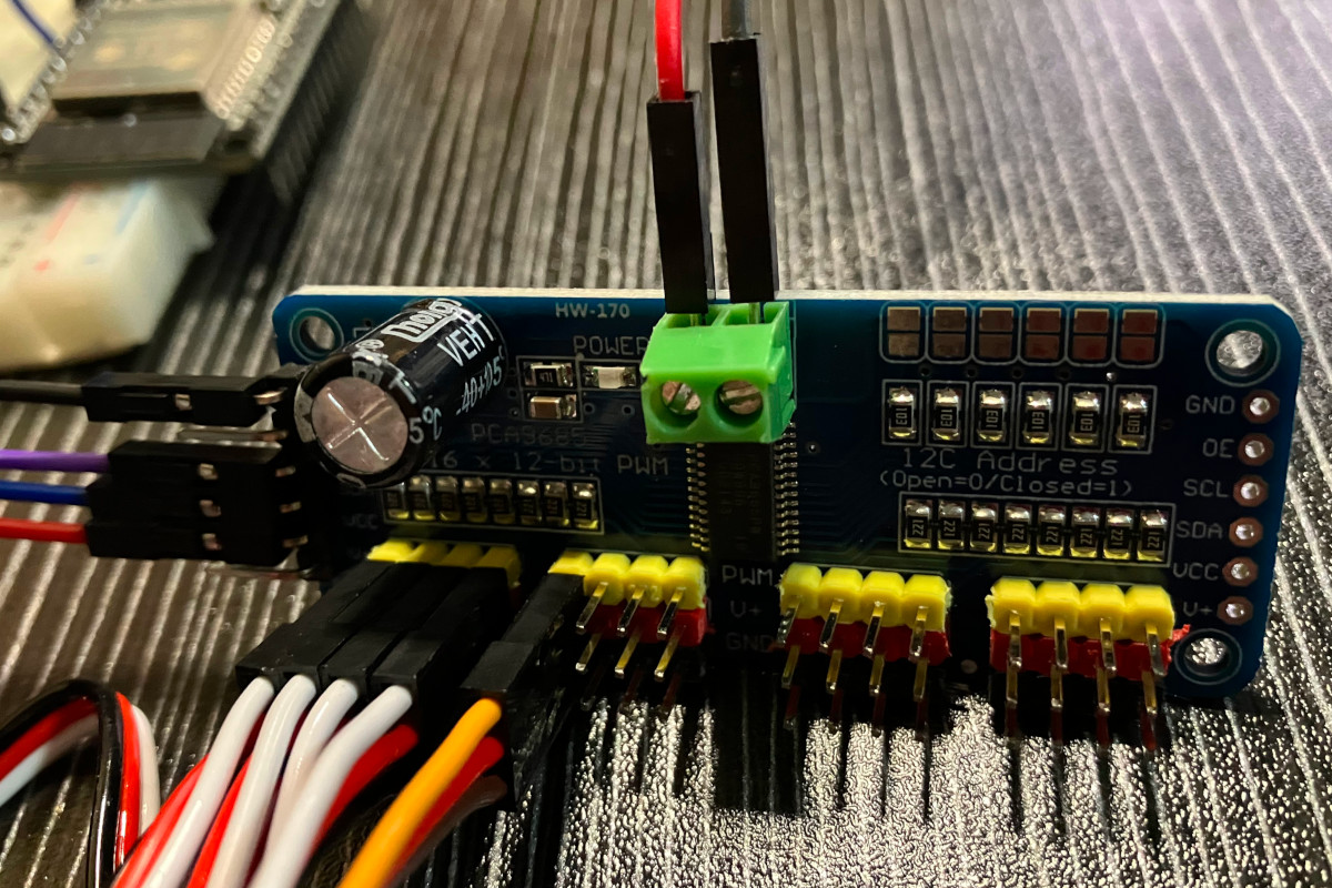
Hardware (PCA9685 Motor driver)

⚫︎ PCA9685 Motor driver

The servo motor is driven by a signal which has a width. When it rotates, it needs to communicate using a proper form of signals. So the motor driver is between the motor and MCU (micro controller like ESP32) for that reason.

Picture of motor driver

Picture of motor driver

Hardware (Servo motor)

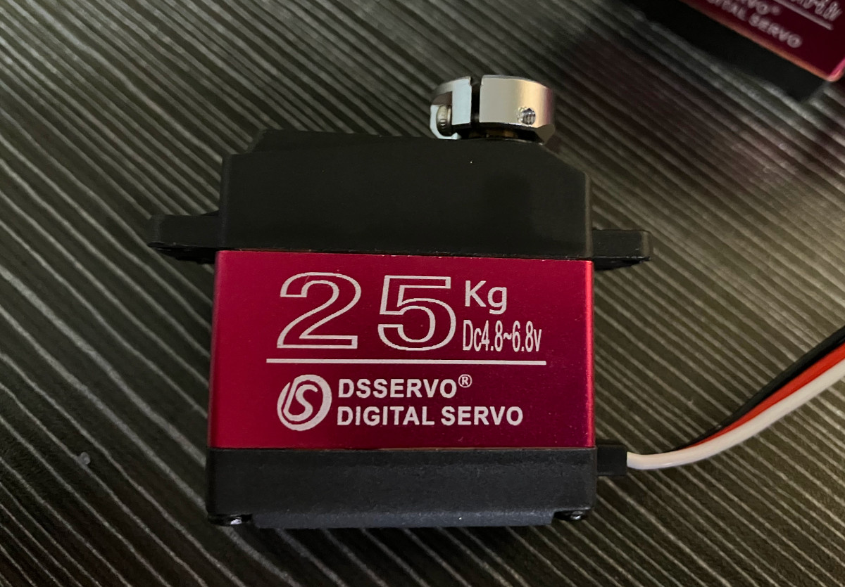
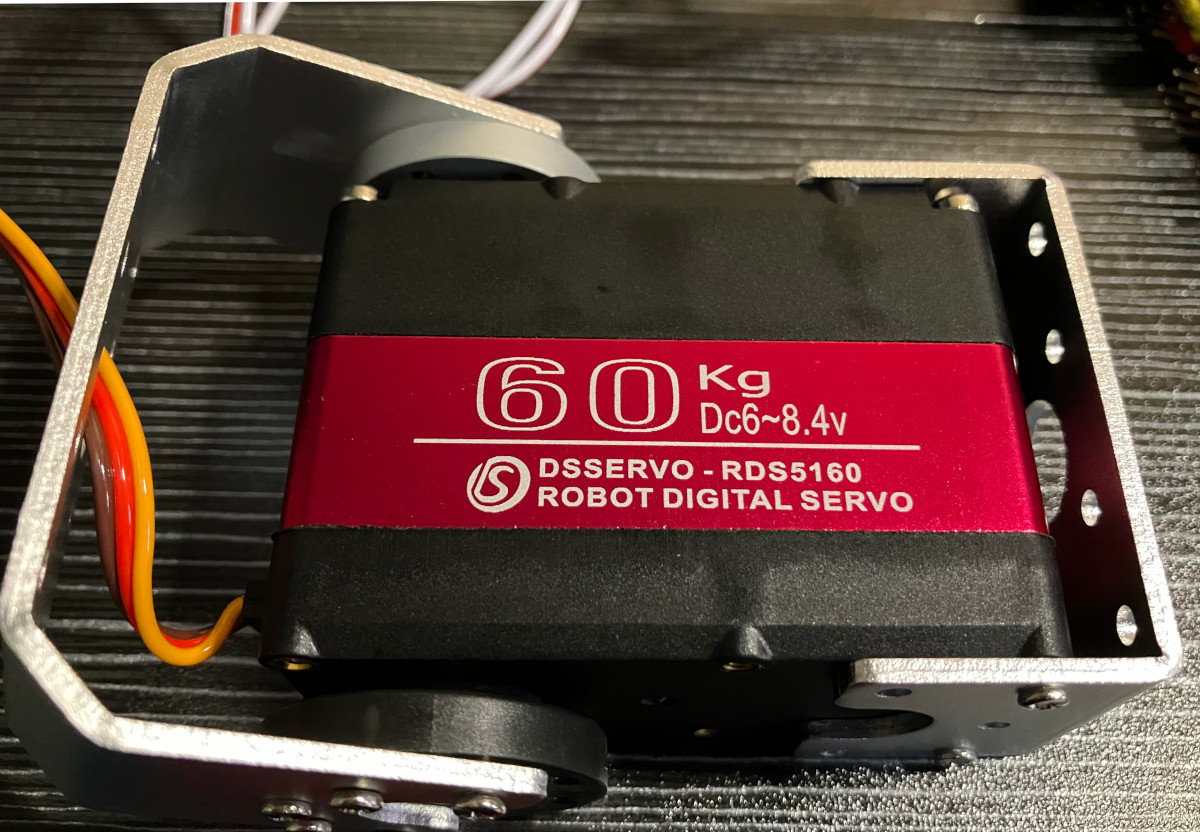
⚫︎ DS3225(25kg Servo) とRDS5160(60kg Servo)

Unlike general-purpose motors, servos aren’t meant for continuous rotation (though some models can rotate). They move to a specified angle in response to a pulse-width signal.

For this exercise we use relatively high-torque servos.

Picture of servo motor (DS3225 25kg)

Picture of servo motor (DS3225 25kg)

Picture of servo motor (RDS5160 60kg)

Picture of servo motor (RDS5160 60kg)

Hardware (ESP32 Devkit)

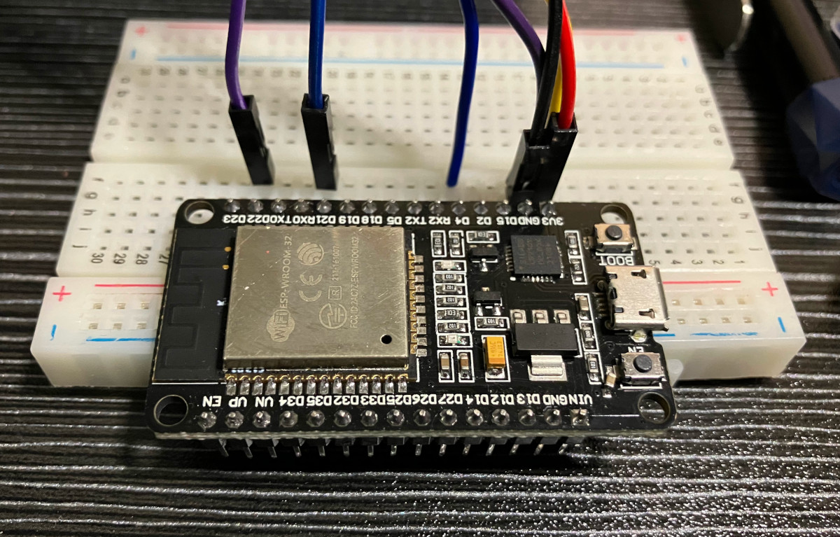
⚫︎ ESP32 Development board

ESP32 is a microcontroller by Espressif. Compared to the well-known Arduino family, ESP32 includes Wi‑Fi and Bluetooth and typically offers more memory.

In embedded systems, though, higher capability often means higher power draw.

That’s why MCU makers offer multiple product lines, each balancing features against power. The variety can feel complex—but it’s also what makes embedded work so interesting.

Picture of ESP32 Development board

Picture of ESP32 Development board

Wiring overview

Wiring overview

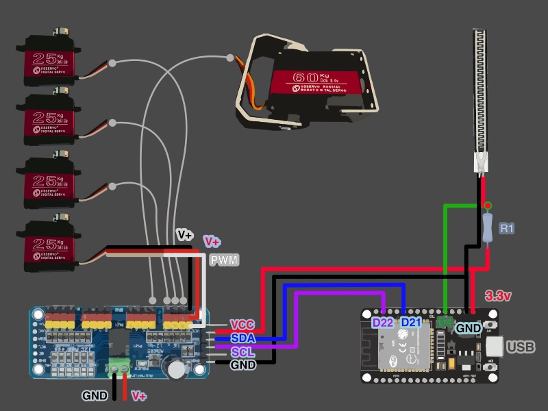
About wiring

Connect the servo to the servo driver module. For each motor, wire three leads: power (+), ground (−), and PWM.

Provide a dedicated power supply to the motor driver so the ESP32 only generates signals, not motor power. Servo current draw varies while moving, and the ESP32 cannot safely supply that power. Use a separate, adequate power source for the servos.

Also connect the flex sensor. Feed the ESP32’s 3.3V through a 10 kΩ pull‑up resistor to the sensor to stabilize the input and prevent floating noise when the sensor isn’t being bent.

3. Code explanation

Code review 1.

// Drive a servo motor with a flex sensor
// by Gounbeee
// coaramause.com
// 2023


// Library to control the PCA9685 motor driver used in this project
//https://github.com/adafruit/Adafruit-PWM-Servo-Driver-Library
#include <Adafruit_PWMServoDriver.h>  


// We will take advantage of the ESP32's two cores:
// Core 0 -> drives the servo motor
// Core 1 -> reads the flex sensor input
// That's the model we want to run.
// 
// To do this, first prepare objects (handles) for the two tasks.
TaskHandle_t tsk1;
TaskHandle_t tsk2;

Explanation 1.

We start by including required libraries. With #include you can reuse code from other files (similar to “import” in other languages). In this project we use Adafruit’s PWM Servo Driver library for the PCA9685.

We’ll use two tasks: one to read the flex sensor and one to drive the servo. That’s why we declare two TaskHandle_t variables.

In C/C++, a “handle” often lets you reference something—like a task—via a pointer (an address in memory) so you can access it later.

Code Review 2.

// --------------------------------------------------------


// Using the library imported above, we will create an object for controlling the servo driver.
Adafruit_PWMServoDriver servoDrv = Adafruit_PWMServoDriver(0x40);

Explanation 2.

Let’s start by creating an object for Adafruit’s servo motor driver. The servo motor driver and the ESP32 communicate using a protocol called I2C (pronounced “I-squared-C”).

Therefore, when creating the servo motor driver object, we specify the memory address as 0x40 for I2C communication.

In the notation “0x40,” the prefix “0x” indicates that the following number, 40, is written in hexadecimal format.

Code Review 3.

// --------------------------------------------------------
// This section contains global information for Task2, which handles the sensor.
// Since this runs as a separate task, caution is needed when referencing the same
// memory locations. During periods when shared data may be rewritten, the values
// might not yet be finalized.
// Therefore, proper inter-task communication (such as waiting for synchronization)
// is sometimes necessary, but we will omit that here.

// This is the PIN with ADC (Analog-to-Digital Converter) functionality.
int sensorPin = 4;


// This stores the information received from the sensor.
// Based on the sensor data, the target position for the servo motor will be calculated.
int sensorValue = 0;

Explanation 3.

Here, we configure the pin used for the sensor — in this case, pin number 4. The variable `sensorValue` is set up to store the data received from the sensor, which will later be used as the rotation angle for the servo motor.

Code Review 4.

// A function that runs once when this sketch starts to prepare required settings
void setup() {

  // Set up Serial communication (USB here) so we can print values
  // using the Arduino IDE's “Serial Monitor”.
  Serial.begin(115200); 


  // --------------------------

  // センサーのためのPIN設定
  pinMode(sensorPin, INPUT);

  // --------------------------

  // Setup for the servo motor driver
  servoDrv.begin();

  // Configure the servos to operate at 60 Hz for this project
  servoDrv.setPWMFreq(60); 


  delay(10);


  // Configure TASKs
  // For the servo motor
  // These refer to the functions defined below.
  //
  // Task1Job : Entry function for the task. This information may be used
  //            when coordinating between tasks.
  // "tsk1"   : Task name. This name may also be used for inter-task coordination.
  // 10000    : The amount of memory this task uses.
  // NULL     : Data to pass to the task.
  // 1        : Priority of the task.
  // &tsk1    : Pointer to the task handle—an entry point to inspect task info.
  // 0        : CPU core number this task will run on.
  xTaskCreatePinnedToCore(
                    Task1Job,   
                    "tsk1",
                    10000,
                    NULL,
                    1,        
                    &tsk1,     
                    0);                  
  delay(500); 


  xTaskCreatePinnedToCore(
                    Task2Job,   
                    "tsk2",    
                    10000,       
                    NULL,        
                    1,          
                    &tsk2,
                    1);       
    delay(500); 


}

Explanation 4.

This section explains the setup function. Although we are using the ESP32, the software uses the Arduino library, so it follows the basic structure (setup function and loop function). Such structures, which seem like fixed rules, are often determined by the software framework being used. This means that when working within a different framework, you may need to use functions with different names. For instance, in the case of ESP32, it can also be programmed using “ESP-IDF,” a C language–based framework (while Arduino uses C++). The code tends to be longer than with the Arduino library, but it allows configuration of the microcontroller at the registry level and enables more detailed settings. Of course, even when using the Arduino library, there are options for finer configuration.

As described in the code comments, this part initializes Serial for output via USB and configures the pin for the sensor. It also sets the PWM cycle using the globally defined servo motor driver object. The servo motor used here can operate at a faster cycle, but for this exercise, it is set to 60 Hz.

Next, two tasks are created using the `xTaskCreatePinnedToCore` function. Previously, only handle variables were prepared, but here the task details are set and the created handles are registered. This function belongs to FreeRTOS, an operating system supported by the ESP32 for embedded systems, and it is called twice to create the two tasks.

A task, in essence, refers to a process that runs independently and continuously. Each task has its own execution loop. As a simplified image, you can think of it as if the setup and loop functions used in the Arduino library are contained within each separate task. The loop itself is written as a for loop without a condition, which means it will never terminate — it’s an infinite loop.

In the settings of the xTaskCreatePinnedToCore function, you need to specify the amount of memory that will be allocated for storing information related to this task. Naturally, the more complex the processing is, the more memory it will require. Since the ESP32 provides two cores, each task is assigned to a specific core number, which must be specified differently for each one.

Finally, note that the first argument of this function registers the name of the function that will be declared next. Inside this function, you will describe the two main operations you want the ESP32 to perform — reading sensor input and controlling the motor rotation.

Explanation 5.

void loop() {
  // We do not use normal loop function.
}

Explanation 5.

The loop function, as mentioned above, is not a feature of FreeRTOS but is provided by Arduino. Therefore, we will not use it this time.

Code Review 6.

// Task 1
// Process to control the servo motors
void Task1Job( void * pvParameters ) {

  // Each TASK must have its own independent loop.
  // The following for-loop provides that structure.
  // Also, it’s good practice to include a small delay (e.g., delay(1)) inside the loop.

  
  for(;;) {

    // Using the servo driver object,
    // apply the sensor readings to the first five motors
    // and rotate them accordingly.
    servoDrv.writeMicroseconds(0, sensorValue );
    servoDrv.writeMicroseconds(1, sensorValue );
    servoDrv.writeMicroseconds(2, sensorValue );
    servoDrv.writeMicroseconds(3, sensorValue );
    servoDrv.writeMicroseconds(4, sensorValue );
    

    delay(10);

  }

}

Explanation 6.

The first task is to “rotate the servo motors.” It is named `Task1Job`, and note that this name is used in the setup function when configuring the task. Tasks are set up by registering handles and function names like this.

Each task must have its own internal loop, so the function that moves the servo motors is written inside a `for` loop.

When a servo motor receives a pulse waveform with a certain time width, it interprets that width as the “angle” to rotate. In the `writeMicroseconds` function, the second argument essentially specifies the “time” sent to the motor, which determines the shape of the pulse waveform.

The first argument of the function specifies the slot number where the motor is connected—here, motors in slots 1 through 5 are moved simultaneously without time delay.

Code Review 7.

// Task 2
// Process to receive input from the sensor
void Task2Job( void * pvParameters ) {

  for(;;) {

    // Receive data from the sensor connected to pin 4 (set earlier)
    sensorValue = analogRead(sensorPin); 
    //Serial.println(sensorValue);
    //Serial.println("  |  ");

    // The flex sensor’s input value ranges from 0 to 4095.
    // However, until the film is bent to a certain degree,
    // it continuously returns 4095, and then suddenly drops
    // to around 1300 and starts fluctuating.
    // To handle this, we artificially reduce the value when it’s 4095
    // (which represents the “not bent” state).
    if (sensorValue == 4095) sensorValue = 2000;

    // Next, we use the map function to scale the value.
    sensorValue = map(sensorValue, 0, 2000, 500, 2000);

    // The servo motors used here accept a pulse width between 500 and 2500,
    // which corresponds to rotation positions from 0° to 270°.
    // To make sure the value stays within that valid range,
    // we use the constrain function to clamp it.
    sensorValue = constrain(sensorValue, 500, 2500);

    Serial.println(sensorValue);

    delay(20);
  }

}

Explanation 7.

Next is the explanation for Task 2. This task handles input from the sensor.

It uses the Arduino library to read analog input from pin 4 via the `analogRead` function. This section also adjusts detailed behavior by testing the flex sensor—tuning parameters such as movement speed and angular limits.

In this type of development, it’s essential not only to test and adjust interactively but also to consult the documentation of the hardware you are using.

The `map` and `constrain` functions are then used to normalize and clamp the input range so that values outside the acceptable servo angle range are not sent.

Finally, a short delay is added; this loop timing corresponds approximately to the servo’s 60 Hz update rate.

4. Wrapping up the exercise

Applying This Exercise

In this exercise, the servo motor was rotated to a specific angle based on how much the flex sensor was bent.

To apply this project, consider where to attach the flex sensor—it could be mounted on a semi-flexible rod or attached to fabric.

Depending on how the flex sensor is bent, it can create interactions related to physical sensation or environmental factors like wind.

← Back to all courses Back to top ↑